Grove - IMU 10DOF
Introduction
Grove - IMU 10DOF is a combination of Grove - IMU 9DOF and Grove - Barometer Sensor (BMP180). This module is base on MPU-9250 and BMP180, the MPU-9250 is a 9-axis MotionTracking device that combines a 3-axis gyroscope, 3-axis accelerometer, 3-axis magnetometer and a Digital Motion Processor(DMP), and BMP180 is a high precision, ultra-low power digital pressure sensors for consumer applications. This module is very suitable for the application of smartphones, tablets and wearable devices.
Specifications
- I2C interface
- MPU-9250 I2C address selectable
- Low Power Consumption
- 400kHz Fast Mode I2C for communicating with all registers
- Digital-output X-, Y-, and Z-Axis angular rate sensors (gyroscopes) with a user-programmable full-scale range of ±250, ±500, ±1000, and ±2000°/sec
- Digital-output 3-Axis accelerometer with a programmable full scale range of ±2g, ±4g, ±8g and ±16g
- Digital-output magnetometer with a full scale range of ±4800uT
- Digital-output barometer with range of 300 ~ 1100hPa(+9000m ~ -500m relating to sea level)
- Dimensions: 25.43mm x 20.35mm
Tip
More details about Grove modules please refer to Grove System
Platforms Supported
Arduino Wio BeagleBone Raspberry Pi LinkIt ONE


Caution
The platforms mentioned above as supported
is/are an indication of the module's hardware or theoritical
compatibility. We only provide software library or code examples for
Arduino platform in most cases. It is not possible to provide software
library / demo code for all possible MCU platforms. Hence, users have to
write their own software library.
| Arduino | Wio | BeagleBone | Raspberry Pi | LinkIt ONE |
|---|---|---|---|---|
 |
 |
 |
 |
 |
Caution
The platforms mentioned above as supported is/are an indication of the module's hardware or theoritical compatibility. We only provide software library or code examples for Arduino platform in most cases. It is not possible to provide software library / demo code for all possible MCU platforms. Hence, users have to write their own software library.
Hardware Overview

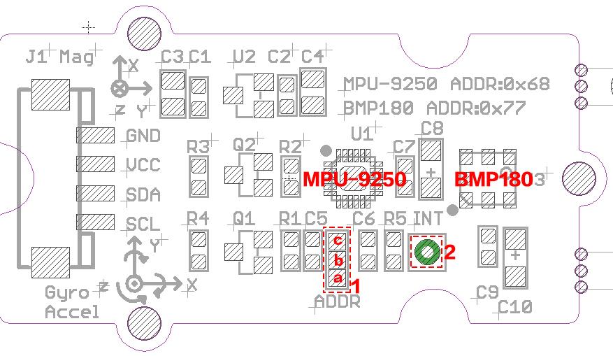
- 1:MPU-9250 I2C address select Pad, default connected a and b address is 0x68, if connect b and c address is 0x69
- 2:MPU-9250 interrupt pin, the interrupt should be configured, available interrupt sources are: motion detection, fifo overflow, data ready, i2c master error
Usage
We will provide an example here to show you how to use this sensor.
Hardware Installation
Software Setup
- Download the library from https://github.com/Seeed-Studio/IMU_10DOF.
- Unzip it into the libraries file of Arduino IDE by the path.
- Open the code directly by the path: File -> Example -> IMU_10DOF_Test.
- Upload the code. Note that you should select the correct board type and COM port.
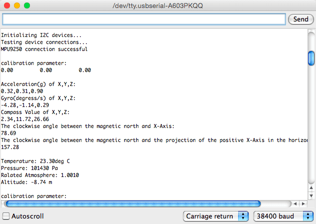
You can see:

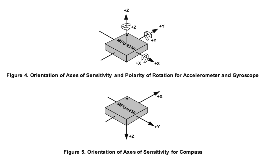
Orientation of Axes
The diagram below shows the orientation of the axes of sensitivity and the polarity of rotation.

Resources
- Grove - IMU 10DOF v1.0 eagle file
- Grove - IMU 10DOF v1.0 schematics pdf file
- Grove - IMU 10DOF v1.1 eagle file
- Get library from github
- BMP180 datasheet
- MPU-9250 datasheet
Help us make it better
Thank you for choosing Seeed. A couple of months ago we initiated a project to improve our documentation system. What you are looking at now is the first edition of the new documentation system. Comparing to the old one, here is the progresses that we made:
- Replaced the old documentation system with a new one that was developed from Mkdocs, a more widely used and cooler tool to develop documentation system.
- Integrated the documentation system with our official website, now you can go to Bazaar and other section like Forum and Community more conveniently.
- Reviewed and rewrote documents for hundreds of products for the system’s first edition, and will continue migrate documents from old wiki to the new one.
An easy-to-use instruction is as important as the product itself. We are expecting this new system will improve your experience when using Seeed’s products. However since this is the first edition, there are still many things need to improve, if you have any suggestions or findings, you are most welcome to submit the amended version as our contributor(Please refer to the tutotrial How to edit a document) or give us suggestions in the survey below, Please don’t forget to leave your email address so that we can reply.
Happy hacking
